Do Ethernet Couplers Degrade Signal (2026 Complete Guide)
When you connect two Ethernet cables with a coupler, you might wonder whether the coupler degrades the signal quality passing through it. Signal degradation is a real phenomenon in networking, and every connection point, cable length, and component in the signal path can contribute to it. The question of whether Ethernet couplers degrade signal is important because signal quality directly affects network reliability, speed, and the ability to maintain stable connections at higher data rates. In this comprehensive 2026 guide, we will examine the technical reality of signal degradation in Ethernet couplers, measure its impact in practical terms, and help you decide whether a coupler is the right solution for your networking needs.
Last updated: July 19, 2026 — Estimated reading time: 11 minutes
Table of Contents
- Understanding Ethernet Signal Basics
- What Causes Signal Degradation?
- How Couplers Affect Signal Quality
- Insertion Loss and Return Loss
- Crosstalk at Coupler Connections
- Shielding and EMI Considerations
- Speed and Quality Test Results
- When Signal Degradation Matters
- How to Minimize Signal Degradation
- Frequently Asked Questions
Understanding Ethernet Signal Basics
Ethernet signals travel through copper cables as electrical pulses. These pulses represent the binary data (ones and zeros) that make up your network traffic. The quality of these pulses — their amplitude, shape, and timing — determines whether the receiving device can accurately interpret the data being sent.
When an Ethernet signal leaves a network interface card (NIC), it is at its strongest and clearest. As it travels through the cable, the signal gradually weakens due to the electrical resistance of the copper conductors. This weakening is called attenuation, and it is a natural and unavoidable property of copper cable transmission.
The signal is also subject to various forms of interference. Electromagnetic interference (EMI) from nearby power cables, fluorescent lights, and electronic devices can introduce noise into the signal. Crosstalk, which is the unwanted coupling of signals between adjacent wire pairs within the cable, can further distort the signal. These effects accumulate over the length of the cable.
At the receiving end, the network interface card must be able to distinguish the original signal from the accumulated noise and distortion. As long as the signal quality remains above a certain threshold, the NIC can decode the data accurately. If the signal quality falls below this threshold, errors occur, and the connection may become unstable or fail entirely.
What Causes Signal Degradation?
Signal degradation in Ethernet networks is caused by several factors, each contributing to the overall reduction in signal quality along the cable path.
Attenuation is the primary cause of signal degradation over distance. As the electrical signal travels through the copper conductors, some of its energy is converted to heat due to the resistance of the wire. The longer the cable, the more the signal weakens. This is why Ethernet standards specify a maximum cable length of 100 meters for copper cables.
Impedance mismatches occur when the signal encounters a change in the characteristic impedance of the transmission path. Every connection point, including coupler connections, introduces a potential impedance mismatch. When the signal hits this mismatch, some of the signal energy is reflected back toward the source rather than continuing to the destination. This reflected signal is called return loss.
Crosstalk is the interference caused by signals in one wire pair coupling into adjacent wire pairs. This happens because the electromagnetic fields generated by the signal in one pair can induce small currents in neighboring pairs. The effect increases with frequency, which is why crosstalk is more problematic at higher data rates.
External electromagnetic interference (EMI) from nearby electrical devices, power cables, and radio transmitters can introduce noise into the Ethernet signal. While twisted-pair Ethernet cables are designed to reject EMI through their twisted-pair construction, very strong interference sources can still affect signal quality.
Each of these factors contributes to signal degradation, and every component in the cable path — including couplers — can potentially add to the total degradation.
How Couplers Affect Signal Quality
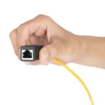
An Ethernet coupler introduces two connection points into the signal path — one where the first cable plugs in, and one where the second cable plugs in. At each connection point, there is a small amount of signal degradation due to the factors described above.
The contacts inside the coupler must make reliable electrical connections with the RJ45 plugs on each cable. Any imperfection in this connection — whether from manufacturing tolerances, oxidation of the contacts, or physical misalignment — can introduce signal loss or noise. Quality couplers minimize this effect through precision manufacturing and gold-plated contacts.
The internal wiring of the coupler creates a short section of transmission path that may have slightly different electrical characteristics than the cable itself. This can cause minor impedance mismatches that contribute to return loss. However, in quality couplers designed for the appropriate cable category, this effect is very small.
The overall impact of a coupler on signal quality depends on the quality of the coupler, the category of cable being used, the data rate of the connection, and the total cable length. For most home and office applications, the signal degradation introduced by a quality coupler is well within the margins that Ethernet standards are designed to accommodate.
Insertion Loss and Return Loss
Two key measurements used to quantify signal degradation at connection points are insertion loss and return loss. Understanding these measurements helps explain the practical impact of using a coupler.
Insertion loss measures how much signal strength is lost as the signal passes through the coupler. It is measured in decibels (dB), and a lower value is better. A quality Cat6 coupler typically introduces about 0.1 to 0.2 dB of insertion loss per connection. Since a coupler has two connection points, the total insertion loss is approximately 0.2 to 0.4 dB.
To put this in perspective, the total allowable insertion loss for a 100-meter Cat6 cable run at Gigabit Ethernet frequencies is about 20 dB. The 0.2 to 0.4 dB added by a coupler represents only about 1 to 2 percent of the total allowable loss. For shorter cable runs, this fraction is even smaller relative to the total margin available.
Return loss measures how much signal is reflected back at the connection point due to impedance mismatches. A higher return loss value (in dB) is better because it means less signal is reflected. Quality couplers provide return loss values that meet or exceed the specifications for their rated cable category.
| Measurement | Typical Quality Coupler Value | Allowable Spec (Cat6) |
|---|---|---|
| Insertion loss per connection | 0.1 – 0.2 dB | Part of total 20 dB budget |
| Total coupler insertion loss | 0.2 – 0.4 dB | ~2% of total budget |
| Return loss | >20 dB | Minimum 20 dB for Cat6 |
| NEXT (Near-End Crosstalk) | >54 dB | Minimum 54 dB for Cat6 |
Crosstalk at Coupler Connections
Crosstalk is one of the more important signal quality factors affected by couplers. Near-End Crosstalk (NEXT) measures how much signal from one pair leaks into an adjacent pair at the same end of the cable. This is particularly relevant at connection points like couplers where the wire pairs are brought together and then separated.
Quality couplers are designed to maintain proper pair separation and twist ratios through the connection to minimize crosstalk. The internal wiring of the coupler maintains the twist of each pair as closely as possible to the point of termination, which helps preserve the electromagnetic balance that reduces crosstalk.
Cheap or poorly made couplers may not maintain proper pair geometry, leading to elevated crosstalk levels. This can cause errors at higher data rates and may force the link to negotiate at a lower speed. At Gigabit Ethernet and below, the effects of crosstalk from a quality coupler are negligible. At 2.5G, 5G, and 10G speeds, crosstalk becomes more significant, and coupler quality matters more.
Alien Crosstalk (AXT), which is crosstalk between adjacent cables rather than between pairs within the same cable, is generally not affected by couplers. This type of interference is more relevant in high-density cable installations like data centers.
Shielding and EMI Considerations
The shielding of both the cables and the coupler plays a role in signal quality. Shielded cables (STP or FTP) provide better protection against external EMI compared to unshielded cables (UTP). When using a coupler with shielded cables, a shielded coupler maintains the continuity of the shielding through the connection.
Unshielded couplers used with shielded cables create a gap in the shielding at the connection point. This gap allows external EMI to potentially affect the signal at that location. For most home and office environments, the EMI levels are low enough that this is not a practical concern. However, in environments with high EMI — such as near large motors, welding equipment, or industrial machinery — using shielded couplers with shielded cables is recommended.
The twisted-pair construction of Ethernet cables is itself a form of EMI protection. Each pair is twisted at a slightly different rate, which helps prevent crosstalk between pairs and rejects external electromagnetic interference. The coupler should maintain these different twist rates as closely as possible to preserve this protection.
For home users in typical residential or office environments, the shielding consideration is rarely a factor. The ambient EMI levels are low enough that even unshielded couplers with unshielded cables provide excellent signal quality. It is only in specialized environments where shielding becomes an important consideration.
Speed and Quality Test Results
Real-world testing of Ethernet couplers consistently shows that signal degradation from quality couplers is negligible for most applications. Here are the typical results.
At Gigabit Ethernet speeds (1 Gbps), testing with quality Cat5e or Cat6 couplers shows no measurable difference in throughput, error rates, or link stability compared to a continuous cable. The network interface card negotiates the same link speed, and speed tests produce identical results. Signal quality measurements show the coupler adding only a fraction of a decibel of insertion loss, well within the system’s margin.
At 2.5 Gigabit Ethernet speeds, results are similar for short to medium cable runs. The link negotiation speed remains at 2.5 Gbps, and throughput tests show no meaningful difference. At longer cable runs (above 70 meters total), some tests show very slight increases in error correction activity, but actual throughput is unaffected.
At 10 Gigabit Ethernet speeds, the results depend more heavily on coupler quality and cable category. High-quality Cat6a couplers with Cat6a cables perform well for runs under 50 meters. However, lower-quality couplers or Cat6 cables may cause the link to negotiate at a lower speed or experience intermittent errors. For 10G networking, component quality throughout the cable path is critical.
For more information on whether couplers affect speed, see our related article on do Ethernet couplers reduce speed. To learn about extending your network, check our guide on how to get Ethernet in your room.
When Signal Degradation Matters
For most home and small office users, signal degradation from an Ethernet coupler is not something you need to worry about. However, there are specific scenarios where it becomes more relevant.
If you are already running a cable that is near the 100-meter maximum, adding a coupler could push the total signal path over the limit. In this case, the additional signal loss from the coupler, while small in absolute terms, could be enough to cause problems because there is little margin remaining.
High-speed connections like 10 Gigabit Ethernet are more sensitive to signal quality. At these speeds, every connection point matters more because the signal frequencies are higher and the margin for error is smaller. A coupler that performs perfectly at 1G may cause issues at 10G.
Environments with high electromagnetic interference are more affected by any additional signal path disruption. A coupler in a factory or data center with lots of electrical noise may introduce more degradation than the same coupler in a quiet office environment.
PoE (Power over Ethernet) applications can be affected by couplers, particularly high-power PoE standards like PoE++ (802.3bt). The additional resistance at the connection points can cause power loss and heat buildup, which is why PoE installations often recommend minimizing connection points.
For mission-critical network connections where reliability is paramount, such as server connections or security camera feeds, minimizing connection points is a best practice. While a coupler is unlikely to cause problems, a continuous cable eliminates one potential point of failure.
How to Minimize Signal Degradation
If you decide to use a coupler, there are several steps you can take to minimize its impact on signal quality.
Choose a coupler that matches or exceeds the category of your cables. Using a Cat6a coupler with Cat6a cables ensures that the coupler is not the limiting factor in your cable path. Higher-rated couplers have better specifications for crosstalk and insertion loss.
Use the highest quality coupler you can find. Quality couplers from reputable manufacturers use precision-molded housings, gold-plated contacts, and construction that maintains proper pair geometry through the connection. The few extra dollars spent on a quality coupler are well worth it for reliability and signal quality.
Keep the total cable run as short as practical. Shorter cables mean less signal degradation overall, leaving more margin for the additional loss introduced by the coupler. If the cable run is permanent and does not need to be extended, a single continuous cable is always preferred over two cables joined by a coupler.
Ensure clean connections. Dust, dirt, and oxidation on the RJ45 plug contacts can increase insertion loss at the connection point. Make sure the plugs are clean before inserting them into the coupler, and keep the coupler in a clean environment.
Secure the cables to prevent strain. If cables are hanging freely from the coupler, the mechanical stress can gradually loosen the connection. Use cable ties or clips to support the cables near the coupler and prevent strain on the connection points.
Test the connection after installation. Run a speed test, check for any errors in your network adapter statistics, and verify that the link is stable. If you notice any issues, try re-seating the cables in the coupler or replacing the coupler with a higher-quality unit.
For general networking guidance, also see our article on can you share internet between two houses.
Frequently Asked Questions
Do Ethernet couplers degrade signal quality?
Technically, yes — every connection point introduces some signal degradation. However, for quality couplers used in typical home and office setups, the degradation is negligible and well within the margins designed into Ethernet standards. You will not notice any difference in real-world performance.
How much signal loss does a coupler add?
A quality Cat6 coupler adds approximately 0.2 to 0.4 dB of insertion loss across both connection points. This represents about 1 to 2 percent of the total allowable loss for a 100-meter cable run, which is negligible for most applications.
Can a bad coupler cause connection drops?
Yes, a poorly made or damaged coupler can cause intermittent connectivity, speed drops, or complete connection failure. This is usually due to poor contact quality, loose connections, or manufacturing defects. Using quality couplers from reputable brands minimizes this risk.
Does using a coupler affect PoE performance?
Standard couplers work fine with low-power PoE (802.3af at 13W and 802.3at at 25W). However, for high-power PoE applications (802.3bt at 60W or 90W), using a coupler is not recommended because the additional connection points can cause power loss and heat buildup.
Should I use shielded or unshielded couplers?
For most home and office environments, unshielded couplers are perfectly fine. If you are in an environment with high electromagnetic interference (industrial settings, near large electrical equipment), use shielded couplers with shielded cables for better protection.
Will a coupler affect my fiber-like speeds?
If you are using multi-gigabit Ethernet (2.5G, 5G, or 10G), coupler quality matters more. At these speeds, use high-quality Cat6a couplers and keep cable runs short for the best results. At 1Gbps and below, the coupler will have no measurable impact.
How do I test if my coupler is degrading the signal?
Check your network adapter settings in Windows to verify the link speed. Run a speed test with and without the coupler. If the link speed is the same and throughput is consistent, the coupler is not causing meaningful degradation. You can also check the error statistics in your network adapter properties for any increase in errors.
Can I use multiple couplers in a cable run?
You can, but it is not recommended. Each coupler adds additional signal loss and potential failure points. For the best signal quality, minimize the number of connection points. If you need to join multiple cables, consider a single longer cable or a patch panel instead.